NoiseKen - Impulse Noise Simulator ( INS series )
Noiseken simulators to reproduce fast rise-up noises which are generated when switching ON / OFF electric current on the inductive load.
Since the pulse includes broadband frequency and its rise-up time is fast at 3ns or less, it can make the noise coupling dense and effective to reproduce the malfunctions of electronics equipment under the test.
It can realize performance evaluation of electronics equipments upon reproduction of line noises which are intruded to the power supply lines or induced noises onto the telecommunication lines.
Discontinuation notice of INS-4020 / 4040 and INS-AX2 series:
In observance of the Minamata convention on mercury, products that include mercury have been restricted of export from Japan. This includes the INS-4020, INS-4040, INS-AX2 series that used a mercury relay switch, and now have been succeeded by the INS-S220. Please take note that the specification of the INS-S220 are not equivalent to that of the previous models.
| Parameter | Specification |
| Pulse setting range① |
Output voltage : 0.50kV ~ 0.99kV ±10% 0.01kV step Pulse width : 100ns ~ 1000ns ±10% 50ns step Variable : 1ms ~ 999 ms ±10% 1ms step |
| Pulse setting range② |
Output voltage : 1.00kV ~ 2.00 kV ±10% 0.01kV step Pulse width : 50ns ~ 1000 ns ±10% 50ns step Variable : 10ms ~ 999 ms ±10% 1ms step |
| Output voltage | 0.5~2.00kV±10% (10V step) |
| Polarity | Positive / Negative |
| Rise time | 3ns Max |
| Putput impedance | 50Ω |
| Termination resistance | 50Ω |
| Pulse repetition mode |
|
| LINE PHASE | 50Hz/60Hz injection phase angle 0~360° ±10°(1° step)Synchronized with L-N of superimposed power supply |
| EXT TRIG |
Operation cycle:10ms Min. Pulse width:1ms Min. Input level:TTL/Open collector negative logic Select LINE PHASE mode, recognized as an external CDN zero-crossing sync signal when there is an input of 16 to 20 ms |
| 1 SHOT | Single output each time the 1 SHOT switch is pressed. Synchronized output at set phase angle in PHASE mode |
| Memory capacity | 5 tests |
| Operating time | 1s~999s ±10% 1s step |
| Superposition phase switching | L(+), N(-), PE / PULSE OUT ※Manual switching by coaxial cables |
| Superposition mode | Common mode / Normal mode ※Manual switching by short plugs |
| EUT power capacity | Single phase AC240V / DC125V 16A (L(+), N(-), PE) |
| Power source/Power consumption | AC100~240V 50Hz/60Hz |
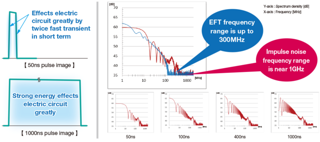
To solve the trouble in the market high frequency, energy volume of test pulse can be adjustable
Even narrow pulse with 50ns-100ns width contains less energy, twice fast transient due to rise and fall and inducted coupling occurred by sharp electromagnetic field effect electric circuit greatly.
Wide pulse with 800ns-1000ns contains more energy, so voltage fluctuation is easily to effect circuit.
The rise time of impulse simulator is faster than IEC61000-4-4 fast transient/burst test, so spectrum is high. When it injects noise to EUT, noise is easier to invade electric circuit internally.
Spectrum and amplitude is different due to Impulse width, so it is recommended to test with different pulse width.
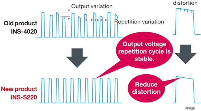
Test reproduction is improved. More quantitative test is available.
The usual mercury relay changes into semiconductor relay, so test pulse stabability is improved. More quantitative and high reproduction test is available. Also, waveform distortion due to mercury relay's deterioration.
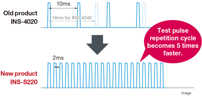
Mal-function rate is up. Test time is to be shortened.
The repetition of pulse in test is faster than the old product. Mal-function rate is up and test time is expected to be shortened.
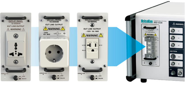
Connection is simplified. Connection time is shortened.
Outlet panel to which EUT is easyily to be connected is adopted.
EUT is easy to connect by using outlet panel ( sold separately ) complying to each country's socket shape.
INS Test Setup Example
Method or test to power supply lines
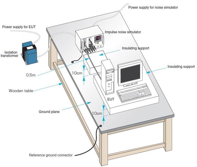
- Connect power supply line for EUT to EUT LINE INPUT on the simulator main unit (hereafter called as main unit) through an isolation transformer
- Lay a ground plane and insulation sheet under main unit and EUT, and ground them for securing
- Connect power supply cable of EUT to main unit (Fold and bind the cable so it can be short in case the length is long)
- Connect short adaptor to SG. Connect SG terminal of main unit and FG terminal (In case it is there) of EUT to ground plane with low impedance braided wire shortly and securely
- Connect 50Ω TERM OUT connector to connector of phase (L1 or L2, PE if necessary) the noise is intended to be injected with coaxial cable
Method or test to interconnection lines
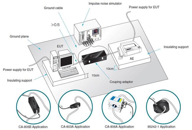
- Lay a ground plane and insulation sheet under main unit and EUT, and ground them for securing
- Open coupling adaptor CA-805B (Option) and clamp interface cable with the adaptor. Connect connector of the adaptor to PULSE OUT of main unit. Connect the one another connector of the adaptor to 50Ω TERM IN of main unit. In case for coupling adaptor CA-803A (Option), connect PULSE OUT of main unit and connector of the adaptor
- Connect power supply cable of EUT to arbitrary power source since no high voltage pulse is injected in this test
- Connect SG terminal and FG terminal of EUT to ground plane
More Product Information

-
Vector Network Analyzer Frequency Range from 10 MHz up to 3.2 GHz
-
Spectrum Analyzer Frequency Range from 9 kHz up to 3.2 GHz
-
-156 dBm/Hz Displayed Average Noise Level (Typ.)
-
-98 dBc/Hz @10 kHz Offset Phase Noise (1 GHz, Typ.)
-
Total Amplitude Accuracy < 1.2 dB
-
1 Hz Minimum Resolution Bandwidth (RBW)
-
All-Digital IF Technology
-
Standard Preamplifier
-
Distance to fault capability using VNA time domain analysis
-
Up to 1.5 GHz Tracking Generator Kit
-
Built-in Advanced Measurement capability (CHP, ACPR, OBW, CNR, TOI, etc)
-
EMI Pre-compliance Test Kit (Opt.)
-
10.1 lnch WVGA (1024 x 600) Display

-
Best solution for high accuracy IV/CV, low-noise and 1/f measurements with PureLine, AutoGuard and next generation MicroChamber technologies
-
Enables up to 5x faster time to accurate data
-
Advanced 4-axis semi-automatic stage for accurate positioning and repeatable probe-to-pad contact
-
RF/microwave device characterization, 1/f, WLR, FA and design debug
-
Wide range of extremly performant, reliable thermal chuck systems from ATT
-
Easy on-screen navigation, wafer mapping, and operation of accessories and thermal systems with Velox
-
User-centered design minimizes training costs and enhances efficiency
See more Key Features on Specifications & Details tab

-
Low noise
-
Excellent line/load regulation
-
Coarse and fine voltage controls
-
Constant voltage or constant current operation with automatic crossover and mode indication
-
Individual On/Off switch per output (not including fixed output)
-
Variable 1.5 -5V output on triple output model
-
Switchable remote sense

-
High-quality construction with low-noise electrical performance
-
Kelvin version for convenient 4-point measurements
-
Replaceable coaxial probe tips, with choice of tip radii, and full electrical guard to the probe tip
-
SSMC 50 connectors
-
Ultra-low, fA and fF measurements from -65 º C to 150 º C

Thin plate broadband antenna has been developed for efficient immunity testing against hand-held transmitters and cellular phones. Many pieces of spot frequency antennas had to be used in turn thus fur. This new Thin-plate Broadband Antenna is a single antenna solution eliminating the need for antenna changes and dramatically reducing the test time. Furthermore, this antenna with its small-size and lightweight properties and a flexible handle is suitable for testing in narrow spaces.
-
A wide frequency range eliminating the need for antenna changes
-
30W maximum power input allows high filed strengths
-
High efficiency due to a low VSWR and high gain
-
Suitable for broadband digital modulation thanks to a good VSWR flatness
-
Small, light-weight and flat antenna easy to use in narrow spaces
-
Easy handling with a flexible arm
-
A wide radiation pattern makes directivity of the fields no longer an issue

-
Low running costs, less vibration, less noise, reduced maintenance
-
Large convenient experimental access: Up to 12 line-of-sight ISO100 ports located on perimeter of plates
-
CMN calibrated thermometry on MC plate
-
Operation via touch panel controller: Remote operation via ethernet interface
")
-
4 GHz or 6 GHz models
-
Up to 5 Vpk-pk dynamic range with low noise
-
±3 V offset range
-
Deluxe soft carrying case
-
Wide variety of tips and leads
-
Solder-In Lead
-
Positioner (Browser) Tip
-
Adjustable (Browser) Tip
-
Quick Connect Lead
-
HiTemp Solder-In Lead
-
-
Ideal for DDR2, DDR3, LPDDR2
-
Low loading and high imedance for minimal signal disturbance

-
Low noise GigE Vision InGaAs SWIR camera
-
VGA resolution
-
Power over Ethernet (PoE+)
-
large pixel with high dynamic
-
Strong sensor cooling, no condensation
-
Very strong sensor cooling for low-noise imaging with long exposure times
-
GigE Vision interface with PoE+
-
Comprehensive I/O control options
-
Automated on-board image correction
-
Extended operating temperature range

-
Light-tight version and EMI-shielded version for low noise and light-sensitive measurements
-
Application flexibility, ideal for use in high frequency applications
-
Sized to accommodate thermal chucks, laser cutter, and video equipment on the probe system
-
Suitable for integration with vibration isolating tables
NoiseKen
For over 40 years from its foundation in 1975, Noise Laboratory has been focusing on immunity test equipment and related solutions.
Now their product lines include various types of immunity test equipment ranging from those conforming to IEC 61000-4 series standards, other international or national immunity standards and even to customer's in-house test standards.
Contact Details
Shinyei Corporation of America Head Office - Sole Authorized distributor of NoiseKen products
1120 Avenue of the Americas, 4th Floor, New York, NY 10036, USA
Phone: 917-484-7884
Fax: 212-704-4206
Test & Measurement
Download Line Card
Document

")