Products
Displaying 949 - 960 of 1197
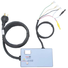
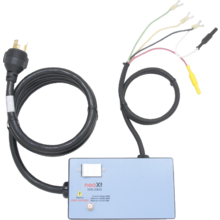
On-Off power switch
30 A Circuit Breaker
Inlet - NEMA L5-30
Outlets – NEMA L5-30R
Test Tap:
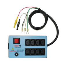
On-Off power switch
15 A Circuit Breaker
Inlet - IEC C14 for use with any cordset
Outlets – (8) IEC C13
Test Tap:
Quick Ship Inventory is available
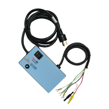
On-Off power switch
20 A Circuit Breaker
Inlet - NEMA L6-20
Outlets – NEMA L6-20R
Test Tap:
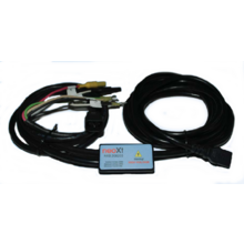
15’ Flexible Power Cord
IEC C13 / C14 Connectors
Test Tap:
3ft.
(2) fork terminals (current)
On-Off power switch
30 A Circuit Breaker
Inlet - NEMA L6-30
Outlets – NEMA L6-30R
Test Tap:
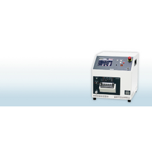
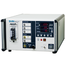
Simulator to reproduce various transient surge phenomena which are generated in a vehicle and required in the international standard ISO-7637-2 (2004) Standard, and evaluate the immune resistibility of the equipped electronics devices against the surge.
ISO 7637-2 (2004) Standard compliant simulator
Correspondent to the test for 12V/24V/42V systems in a vehicle
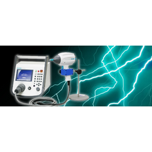
Electrical fast transients (EFT), such as switching transients originating from inductive load interruption, relay contact bounce, etc., are one of the main causes of equipment malfunctions. Because they can occur anywhere interfering with circuits primarily via mains and interconnection cables.
Reproduces transient voltage surge phenomena generated in a vehicle and evaluates the immune resistibility of DUT against the surge. The output waveforms are five as high-repeating pulse, giant pulse, field decay pulse, trapezoidal waveform + high-repeating pulse and high repeating pulse + giant pulse.
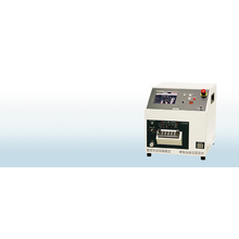
This model is for carrying out a high pressure noise test of individual automotive manufacturers' demands. It simulates representative high voltage noise of HV and EV.
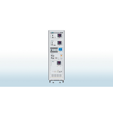
Single-phase 3 wire
AC85 - 240V16A
50/60Hz
DC125V16A
Pulse: ~ 500V 50kHz (option)
Noiseken simulators to reproduce fast rise-up noises which are generated when switching ON / OFF electric current on the inductive load.
Since the pulse includes broadband frequency and its rise-up time is fast at 3ns or less, it can make the noise coupling dense and effective to reproduce the malfunctions of electronics equipment under the test.
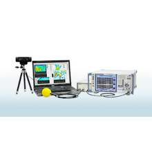
The system detects position of the magnetic field sensor on the basis of the image on the camera first of all and then, recognizes strength of the signal that is measured by the sensor upon frequency analysis of the signal almost simultaneously. Finally, visualization of the strength level in composition with the real image of the measured object can be realized on screen of PC in form of heat map in colors.
