Focus Microwaves - Noise Measurement System Up to 170 GHz
Focus Microwaves introduces a cutting-edge noise measurement system comprising three integral components: the Input Noise Module (INM), Output Noise Module (ONM), and Noise Module Controller (NMC). This system extracts precise noise parameters, offering rapid, stable measurements and optimized performance with dedicated software for calibration and analysis.
Focus Microwave’s wide-band Noise Measurement system is a cutting-edge solution that covers an expansive frequency range from 0.5 to 170 GHz, making it one of the industry’s most comprehensive noise measurement systems available. This system is designed to facilitate the accurate extraction of the four essential noise parameters of a device under test (DUT):
- Minimum Noise Figure (NFMIN): Represents the lowest achievable noise figure of the DUT.
- Equivalent Noise Resistance (RN): Refers to the equivalent noise resistance presented by the DUT.
- Optimum Noise Reflection Factor (Magnitude, Phase): Indicates the optimum noise reflection factor of the DUT in terms of magnitude and phase for optimal noise performance.
The noise measurement system caters to both connectorized and bare die devices, offering versatility in device compatibility. Furthermore, it provides fast, precise, and stable measurements crucial for accurate noise analysis within the specified frequency range.
The system comprises three key components:
- Input Noise Module (INM)
- Output Noise Module (ONM)
- Noise Module Controller (NMC)
These modules work in tandem to improve precision and sensitivity in noise receiver performance, simplify system calibration procedures, and enhance the DUT measurement process. The direct probe mounting of the source tuner and the utilization of the new Delta series noise modules set a new standard in the industry, elevating sensitivity, expanding the dynamic range, and ensuring comprehensive coverage across a broad frequency band.
Models & Specifications
Setup
More Product Information

- High power density up to 150 kW in a single bay rack-mount cabinet. Up to 240 kW in a dual bay rack.
- Fast load transient response provides protection from undesired voltage excursions.
- Fast slew rate with exceptional rise/fall times for speed-critical applications.
- Low ripple suitable for the most sensitive applications.
- Low audible noise with temperature controlled variable speed fans.
- High accuracy voltage/current measurements without external DMMs.
- Modular architecture simplifies sparing and maintenance.

Discover Focus Microwaves' versatile MMT series of manual tuners, offering octave and multi-octave bands from 400MHz to 18GHz. With the same RF technology and precision as our automatic tuners, they ensure high VSWR at the DUT reference plane for reliable performance. Enhance harmonic tuning with options -H2 and -H23, inspired by our harmonic rejection tuners (PHT). Experience precision in manual tuning with Focus Microwaves.

-
High SNR mode (up to 24 dB better signal-to-noise ratio)
-
Low-noise binning mode
-
Smear reduction
-
Shading correction
-
Area of interest (AOI), separate AOI for auto features
-
Binning
-
Decimation
-
Auto gain (manual gain control: 0 to 24 dB)
-
Auto exposure (27 µs to 67 s)
-
Auto white balance
-
Look-up table (LUT)
-
Hue, saturation, color correction
-
Reverse X
-
Deferred image transport
-
Trigger programmable, level, single, bulk, programmable delay
-
Sequence mode (changes the camera settings on the fly)
-
SIS (secure image signature, time stamp for trigger, frame count)
-
Storable user sets

Discover the frontier of tuner technology with Focus Microwaves' new waveguide tuners, designed for frequencies exceeding 110GHz. Combining the success of DELTA and omega tuners, these instruments promise to revolutionize Sub-THz bands, offering a high tuning range in a compact footprint. With extreme precision and low-loss RF probes, these tuners ensure optimal accuracy and repeatability, setting a new standard in on-wafer applications.
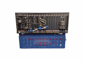
Auriga’s 5th generation pulsed IV/RF characterization system delivers unparalleled performance, capturing measurements with incredible speed and accuracy. Pulsed IV (current-voltage) measurements have emerged as the preferred method of capturing current-voltage characteristics of active devices such as field effect (FETs) and bipolar junction (BJTs) transistors.
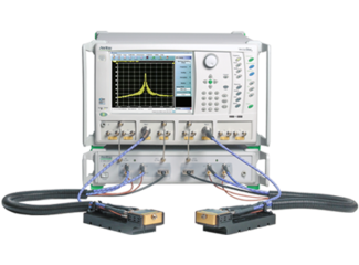
The VectorStar ME7838 Series broadband VNA offers the widest available single frequency sweep from 70 kHz to 110, (ME7838AX to 125), (ME7838EX to 125), to 145 GHz, and to 220 GHz with mmWave bands to 1.1 THz.
- The ME7838AX or ME7838EX version can easily be upgraded to 145 GHz and to 220 GHz
- All versions may be configured to include banded millimeter-wave modules up to 1.1 THz
- Industry-best calibration and measurement stability: 0.1 dB vs 0.6 dB over 24 hrs.
- All versions support the 3744x-Rx receiver for noise figure measurements, including the ability to characterize differential noise figure, to 125 GHz
- Compact, lightweight mmWave modules (0.6 lb vs 7+ lbs and 1/50 the volume) offer low cost installation on smaller probe stations.
Focus Microwaves’ RAPID DT, built on Keysight’s M5000 PXI modules, delivers fast, broadband load pull and S-parameter testing up to 18 GHz. It supports CW and pulsed signals across wide bandwidths, making it ideal for advanced standards like 4096QAM 802.11be.

- 3 Measurement States; Quiescent (OFF-State), Non Quiescent (ON-State), and Pre-State
- The Pre State is a short high voltage state used to activate the traps in the semiconductor.
- Adjustable delay (Δt) between the Pre state and Non Quiescent state down to 0s.
- Independently adjustable timing settings for the Three-state gate pulser and drain pulser
- Easy Integration into existing mainframes

-
APS-H optical format CMOS sensor
-
PoCXP
-
4-DIN type connector
-
79.7 fps at full resolution
-
Extended near-infrared (X-2620B NIR) model
-
Extended feature set with Sequencer Control and Multiple Region of Interest selection to support advanced imaging applications
-
On-board Defect Pixel and 2D Fixed Pattern Noise Correction for improved image quality
-
Simplified firmware update in the field via interface cables using GenICam File Access
-
Robust, fan-less design for industrial imaging applications
-
Heat-dissipation optimized housing to reduce image noise
-
Build-in tripod adapter and multiple mounting holes for eased system integration
-
DIN 1.0/2.3 CoaXPress connectors for secure operation in industrial environments
-
Single cable solution using Trigger and Power over CoaXPress
-
Comprehensive I/O functionality for extended control of connected system components
-
Select between B 270 ASG protection glass and filter types: IRC30 IR cut filter or Schneider 486 IR cut filter

Focus Microwaves
Focus Microwaves is a pioneering engineering company, built around the innovations of its founder Dr. Christos Tsironis who developed his first manual tuner in 1973 and is the inventor of most existing electro-mechanical tuner families. The success of Focus is based on the engineering and manufacturing skills of its highly motivated and experienced team of engineers and technicians, who have been trained and encouraged to develop new technologies. In addition, listening to our customers needs and insights helps us discover and develop new and measurement methods on an ongoing basis, relentlessly pushing the limits of what is possible.
From humble beginnings in 1988, Focus has become the main supplier of advanced Load Pull and Noise Tuner Systems. Our mission is to provide effective, reliable and innovative solutions for non-50 Ohm testing (Noise and Load Pull) of RF microwave transistors, thus enabling our customers to compete in the marketplace with better designs and to advance the understanding and knowledge of the field.
Contact Details
Focus Microwaves Inc. Main Head Office
4555 Chem. du Bois-Franc, Saint-Laurent, QC H4S 1A8, Canada
Phone: +1-514-684-4554
Test & Measurement
Download Line Card