Focus Microwaves - Scalar Load Pull Test Software
Scalar Load Pull
This is a classic form of loadpull where a pre-calibrated source and load tuners are connected directly at the input and output of the device. The precise moment of the pre-calibrated tuners allows generation of complex reflection factors in highly repeatable manner.
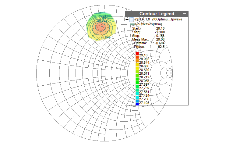
Power meters at the input of the source and output of the load tuners are connected through couplers to search for the optimal gain and output power by synthesizing the source and load impedence using the pre-calibrated tuners. The optimum load impedence extracted is the complex reflection factor where maximum output power is measured using the maximum power transfer theorem. Similarly, at the input side the optimum source impedence is the point where maximum transduces gain is measured. The optimum load and source impedence are completely dependent upon the pre-calibrated tuners repeatability.
Setup
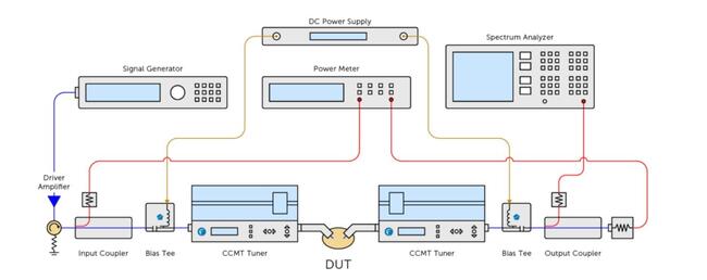
The typical scalar load pull setup comprises a signal generator, two RF power sensors, a power meter, some DC bias networks and two fundamental tuners. The input and output passive block comprising of couplers, bias tees are also pre-calibrated, and S-Par are defined in the measurement setup.
Parameters
The parameters measured using the scalar loadpull setup are:
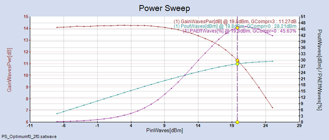
- ΓLoad, Γsource
- All spectral quantities like ACPR, EVM and Harmonic Power levels are measured by connecting a Spectrum Analyzer at the output.
Vector Load Pull
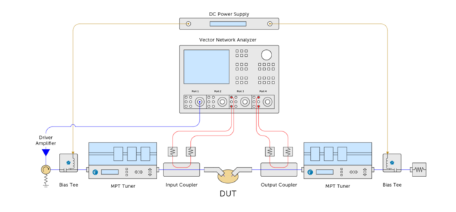
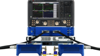
More advanced loadpull setup is referred as Vector loadpull or VNA assisted loadpull. In this measurement setup the forward (a1,b1) and reverse (a2,b2) travelling waves are measured using the two directional couplers connected at the input and output of the DUT. Measuring “a” and “b” waves forms allows vector loadpull to calculate the real time tuner impedence presented to the DUT and does not fully rely on tuner calibration and repeatability. However, tuner calibration is useful to be able to steer tuning into right area of the smith chart without long search.
The typical vector loadpull comprises of two directional couplers, source and load tuners and the Vector Network Analyzer with receiver access capability. An absolute calibration at DUT reference plane is required to fully compute the 8-term error model, without leaving composite terms, as is the case for a standard small signal calibration.
Setup
A vector Loadpull setup can be upgraded to hybrid Active Loadpull and time domain measurements using the relevant hardware.
Parameters
The measured RF parameters include:
- PAE, ACPR
- ΓLoad, ΓIN
In this measurement setup both Power In delivered to the DUT and the PAE are calculated using the captured waveforms. All RF parameters are captured in a single shot which dramatically increases the measurement speed. All harmonic power levels are also measured by the Vector receiver.
Pulsed Load Pull
For high power non-linear devices, the self-heating and memory effects severely affect the performance when excited in the continuous wave mode. Using pulsed stimulus signals, the device can be characterized at the higher peak power levels up to saturation to which the devices will be subjected in their intended use. If the devices are excited in pulsed mode, they can be operated at higher peak power level at a reduced risk of device breakdown and a better control of operating temperature. In many applications Pulsed approach represents a realistic operation for devices, like RADARs.
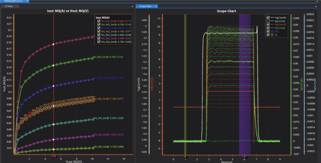
Another important application of pulsed measurements is pulsed I-V and pulsed S-parameter. This approach has been widely used to extract electro thermal models of different device technology. Pulsed operation when combined with high DC voltage levels can also be very interesting for the validation of nonlinear models which considers thermal and trapping effects and can be used to test large devices that could not be tested at the same power levels under CW conditions due to excessive self-heating.
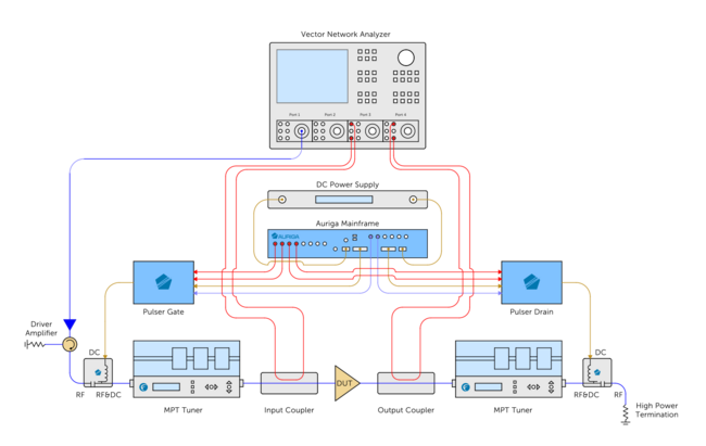
In Pulsed LP measurements both DC and RF can be pulsed. A pulsed load-pull test bench comprises of pulsed bias tees, a primary DC pulse generator, RF source synchronized to a pulse generator, and digitizing scope. The digitizing scope is used to monitor the Pulsed DC characteristics within the pulse. Focus LP uses two different options for Pulse generators, AU5 or MPIV. All passive components of the test setup (including the programmable tuners) are wideband enough to let the pulsed signal pass without any distortion.
For RF characterization there are two different scenarios
1. Scalar LP
Peak power meters synchronized to primary pulsing instrument are used to monitor the RF power within the pulses.
2. Vector LP
Measurements are made using the Vector Network Analyzer receivers which are synchronized with the primary pulsing instrument.
Setup
Parameters
The measured RF parameters include:
- PAE, ACPR
- ΓLoad, ΓIN
Active Load Pull
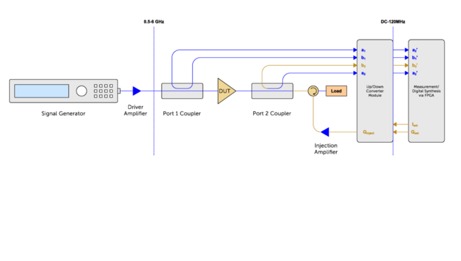
Active load pull tuning is, because of limited tuning range of passive tuners, additionally reduced by fixture and probe insertion loss, the only method allowing test engineers to reach up to |Γload|=1 (RDUT=0Ω) to match any DUT at its reference plane. In closed loop active tuning, part of the extracted RF power from the DUT is amplified and fed back into the DUT output port, creating a virtual load. Since the re-injected power can be higher than the original extracted power, Γ can be >1, meaning that insertion loss can be compensated. Using two (or more) synchronized (coherent) sources allows open-loop active (and harmonic) tuning; in fact the loop here is also closed, but, instead at RF, it is closed at IF synchronizing reference.
Setup
Parameters
Modulated
WideBand Impedance Tuning
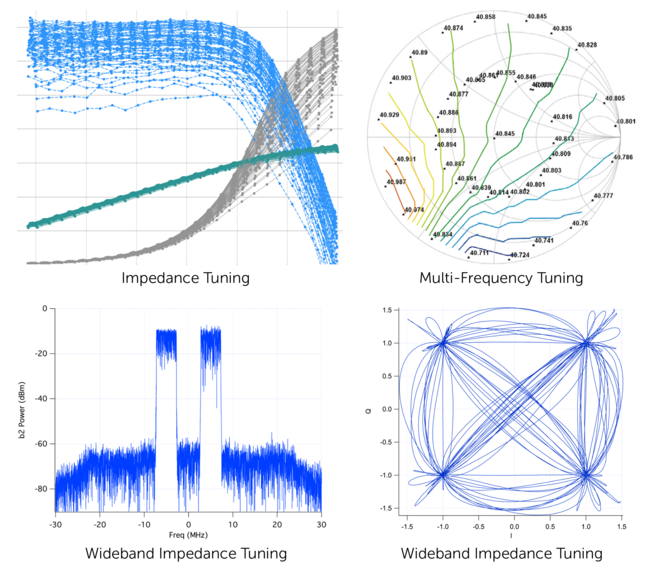
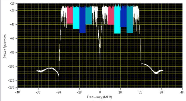
As communication standards require more and more channel bandwidth the need for wideband tuning is increasing. Wideband impedance tuning is now possible as RAPID’s active loop has 100MHz of instantaneous bandwidth allowing users to perform real time modulated measurements. Many spectrum analysis features are also available, such as ACPR, EVM, CCDF, Spectrum mask for advanced modulation standards like LTE and 802.11a/b/g/n/ac.
Active Hybrid Load Pull
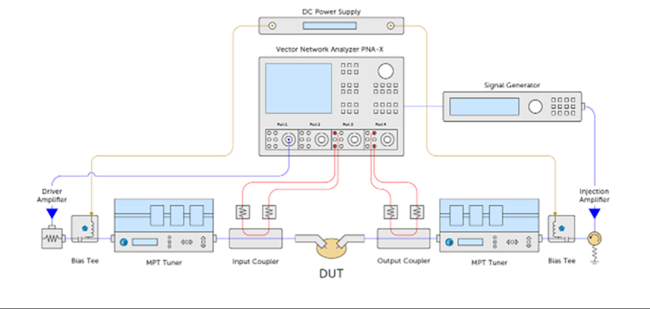
Vector receiver based loadpull setup can be upgraded to a hybrid setup. As per its name a hybrid load pull system includes both an active loop as well as the passive tuners. The hybrid system has all the advantages of speed and tuning range of an active system as well as the power handling of a passive system.
Mechanical tuners due to their inherent passive nature have limitations in terms of impedence synthesis for devices with very low impedence, meaning realization of impedence at the edge of the smith chart. These limitations add up when any loss between tuner and DUT reference plane is introduces as in case of On-wafer vector loadpull where a coupler and RF probes are added between the tuner and DUT reference.
The principle of operation for hybrid LP is that the passive wideband (fundamental) tuner creates a reflection factor near the optimum load impedance (which cannot be reached using the passive tuner alone) and the active power injection creates the additional reflection factor needed to reach the border of the Smith chart (Γ=1). Because the mismatch conditions are better, the required power to be injected is, typically, lower than in the case of full Active LP.
Setup
To increase the reflection factor at the probe tip (DUT) and minimize the power loss we must maximize S21 and minimize S11. Any mismatch loss must be compensated by additional injected power in a hybrid (active/passive) tuner.
Parameters
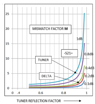
Hybrid tuning is not a panacea. Whereas it allows high VSWR at DUT reference plane, it still remains a rather complex test system with feedback power amplifiers and, often, a second, synchronized, signal source, plus the requirement for in-situ vector power wave measurement, possible through directional couplers inserted between the DUT and the tuner; this on the other hand reduces the tuning range and increases the need for even higher power amplifiers. Passive pre-matching tuning in hybrid systems reduces the requirement for high power from the feedback amplifiers, but only to some extent: passive tuners are not lossless. Tuner loss increases rapidly with reflection factor and so does the power requirement. The critical quantity in tuner loss calculations is “mismatch loss”.
Mismatch loss is S212/(1-S112)
For high S11 values, as needed to pre-match for enhancing the passive reflection factor with active injection in a hybrid configuration, it happens that any increase in insertion loss S21 (due to cables, adapters etc. between tuner and DUT) is multiplied by a factor M=1/(1-S112).
Typical values of the multiplication factor:
S11=0.9 (VSWR=19:1) -> M=5.3
S11=0.96 (VSWR=50:1) -> M=13
Time-Domain Load Pull
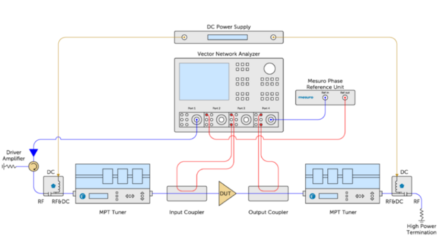
The Vector loadpull setup can be extended to fully calibrated time domain measurements by adding a phase reference. A phase reference is a device that has been pre-characterized to uncover the phase relationships between the fundamental and harmonic frequencies.
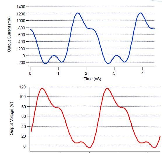
Time domain characterization technique is aimed at high power, non-linear devices that allows insight in process characteristics, comparisons to knee and breakdown voltages, and to have the ability to place the device into a known class of operation and view the resultant waveform. The shaping of current and voltage waveforms real time in the measurement cycle by accurately terminating the fundamental and harmonic frequencies enables the designer to choose the correct PA mode of operation and how to achieve it.
Setup
Parameters
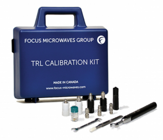
First step in time domain measurement characterization is the standard small signal calibration, based on established techniques e.g. TRL which are Ratio measurements which ends up with composite error terms. The absolute calibration involves reference to known standards in terms of power and phase. Absolute power calibration is achieved with a calibrated power meter. For relative phase (time) a pre-calibrated phase reference HPR is used.
The measured RF parameters include:
- PAE, ACPR
- ΓLoad, ΓIN
- Loadlines
More Product Information
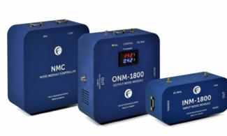
of the cold-source noise figure measurement technique. This specific technique requires a noise source to determine the kBG (gain-bandwidth constant) of the system and a passive mechanical tuner is used to characterize the noise receiver across both the impedance and frequency space. This step is imperative to obtain fully vector-source-corrected measurements.
A RF down conversion stage might be required if the frequency of noise measured exceeds the receiver’s bandwidth. Focus offers noise modules which support down conversion for optimal speed and performance.
-
Type APS-H CMOS sensor
-
IEEE 1588 PTP
-
Power over Ethernet
-
4.59 fps at full resolution
-
Extended near-infrared (GT5120NIR) model
-
GigE Vision interface with Power over Ethernet
-
Screw mount RJ45 Ethernet connector for secure operation in industrial environments
-
Supports cable lengths up to 100 meters (CAT-6 recommended)
-
Trigger over Ethernet Action Commands allow for a single cable solution to reduce system costs
-
Comprehensive I/O functionality for simplified system integration
-
Planarity adjusted (PA) EF Lens Mount (option -18) for electronic control of aperture and autofocus
-
Easy camera mounting via standard M3 threads at all sides and 1/4-20 tripod mounting hole
-
Easy software integration with Allied Vision's Vimba Suite and compatibility to the most popular third party image-processing libraries.
-
Enhanced Defect Pixel Correction feature with a new Defective Pixel List Manager tool that allows you to load different user defined defective pixel lists to match your application and optimize the life cycle of the camera
-
3 Measurement States; Quiescent (OFF-State), Non Quiescent (ON-State), and Pre-State
-
-
The Pre State is a short high voltage state used to activate
the traps in the semiconductor.
-
-
-
Adjustable delay (Δt) between the Pre state and Non Quiescent state down to 0s.
-
Independently adjustable timing settings for the Three-state gate pulser and drain pulser
-
Easy Integration into existing mainframes
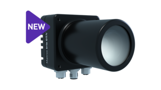
- Boost performance by up to 3x over its precursor thanks to an Intel x6000 series embedded processor
- Capture high-resolution images at high speed through a choice of CMOS sensors from two to 16 Megapixels
- Deploy in dirty, humid, or harsh industrial environments by way of a compact IP67-rated design
- Communicate actions and results to other automation and enterprise equipment via real-time digital I/Os, and Ethernet (TCP/IP, CC-Link IE Field Basic, EtherNet/IP™2, Modbus® , PROFINET® , and native robot interfaces)
- Handle Human-Machine Interface (HMI) function by way of VGA and USB connectivity
- Simplify vision setup and upkeep via integrated lens focusing and illumination intensity control
- Synchronize to the manufacturing line through the support for incremental rotary encoders
- Solve machine vision applications efficiently with Aurora Design Assistant by constructing flowcharts instead of writing program code
- Maintain control and independence through the ability to code custom flowchart steps
- Tackle machine vision applications with utmost confidence using field-proven tools for analyzing, locating, classifying, measuring, reading, and verifying
- Leverage deep learning for visual inspection through image classification and segmentation tools
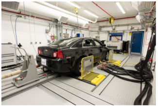
The automotive industry is a sector frequently on the cusp of transformation. Fast-paced industry shifts span technology innovations, regulatory standards, green initiatives, and customer expectations, influencing manufacturers’ testing needs, growth objectives, and overall business strategies. Companies striving for a competitive edge focus on sustainable practices, regulatory compliance, and innovation in Electric Vehicles (EVs), alternative fuels, and autonomous driving systems. This positions the automotive industry in vital need of testing facilities that are future-proofed for rapid and ongoing transformation.
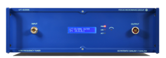
The low frequency tuners are a unique product technology using MPT algorithms for low frequency wideband tuning. Three or more cascaded tuning sections use series transmission cables and parallel rotary capacitors.
The length of the cables and number of tuning sections are optimized for maximum tuning range over a given bandwidth. HLFT tuners use 6 tuning sections allowing second harmonic frequency tuning.

Focus Microwaves
Focus Microwaves is a pioneering engineering company, built around the innovations of its founder Dr. Christos Tsironis who developed his first manual tuner in 1973 and is the inventor of most existing electro-mechanical tuner families. The success of Focus is based on the engineering and manufacturing skills of its highly motivated and experienced team of engineers and technicians, who have been trained and encouraged to develop new technologies. In addition, listening to our customers needs and insights helps us discover and develop new and measurement methods on an ongoing basis, relentlessly pushing the limits of what is possible.
From humble beginnings in 1988, Focus has become the main supplier of advanced Load Pull and Noise Tuner Systems. Our mission is to provide effective, reliable and innovative solutions for non-50 Ohm testing (Noise and Load Pull) of RF microwave transistors, thus enabling our customers to compete in the marketplace with better designs and to advance the understanding and knowledge of the field.
Contact Details
Focus Microwaves Inc. Main Head Office
4555 Chem. du Bois-Franc, Saint-Laurent, QC H4S 1A8, Canada
Phone: +1-514-684-4554
Test & Measurement
