You design the future. We help you make it happen.
Schloder - Conducted Immunity Test Set
See "Specifications & Details" tab for more information.
|
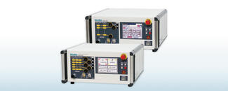
The CDG 7000 is a new test generator for all standards on immunity to conducted disturbances induced by high-frequency fields - including BCI tests (ISO 11452-4).One of the very few combined IEC 61000-4-6 test systems that contain the RF signal generator, an RF power amplifier, a 3-channel RF voltmeter, and a directional coupler at a very affordable price. The CDG 7000 generates interference in accordance with IEC / EN 61000-4-6 - immunity to conducted interference that is induced by high-frequency fields. The standard describes a test setup in which this high-frequency interference can be influenced on a test item without a complicated setup with antennas, field instrumentation, and shielded rooms. The use of coupling networks and coupling tongs induces sine waves directly in power and signal lines. The device under test retains its original position in the device structure so that the overall function of the system can be tested. |
Features
- The compact device consists of an RF signal generator, an RF power amplifier, a 3-channel RF voltmeter, and a directional coupler
- Frequency range (signal generator) 4 kHz - 1200 MHz
- The RF power amplifier is available in three different versions
- The supplied application software ( HELIA 7 - Basic ) enables extensive reporting functions and EUT monitoring, (HELIA 7 - BCI required for BCI tests)
- Easy expansion with an external amplifier via 2nd generator output
- SCPI command set enables easy integration into your own software systems
- Interfaces: USB , LAN , GPIB (option)
- Temperature measurement input, eg for monitoring and displaying the BCI staple temperature
- External pulse modulation input
- Configurable, digital 8-channel user connection
- Warranty 3 years
|
CDG 7000-25 |
Conducted RF generator, acc. IEC 61000-4-6, 100 kHz – 250 MHz, amplifier 25WMaximum test level: 10 V (15 V) with 80% AM (without 6 dB) Built-in directional coupler, with software HELIA 7 - Basic USB, LAN |
|---|---|
|
CDG 7000-75 |
Conducted RF generator, acc. IEC 61000-4-6 100 kHz – 400 MHz, amplifier 75WMaximum test level: 30 V (40 V) with 80% AM (without 6 dB) Built-in directional coupler with software HELIA 7 - Basic USB, LAN |
|
CDG 7000-75-10 |
Conducted RF generator, acc. IEC 61000-4-6 10kHz – 250 MHz, amplifier 75WMaximum test level: 30 V (40 V) with 80% AM (without 6 dB) Built-in directional coupler with software HELIA 7 - Basic USB, LAN |
|
RF-Power Amplifier |
|||
|---|---|---|---|
|
25 W |
75 W |
75 W / 10k |
|
|
Frequency range |
100 kHz-250 MHz |
100 kHz-400 MHz |
10 kHz-250 MHz |
|
Output Power: |
|||
|
Nominal |
25 W |
75 W |
75 W |
|
Linear @ 1dB compression |
20 W |
50 W |
50 W |
|
Gain |
46 dB nominal |
51 dB nominal |
51 dB nominal |
|
Flatness |
± 1.5 dB maximum |
± 1.5 dB maximum |
± 1.5 dB maximum |
|
Input power for rated output |
1 mW / 0 dBm |
1 mW / 0 dBm |
1 mW / 0 dBm |
|
Input / output impedance |
50 Ω |
50 Ω |
50 Ω |
|
Input VSWR |
1.5 : 1 max. |
1.5 : 1 max. |
1.5 : 1 max. |
|
Harmonic distortion |
< -20 dBc @ 20 W |
< -20 dBc @ 50 W |
< -20 dBc @ 50 W |
|
Noise figure |
typ. 5 dB |
typ. 7 dB |
typ. 7 dB |
|
Spurious output |
< -75 dBc at 10 W |
< -75 dBc at 10 W |
< -75 dBc at 10 W |
|
RF Generator |
|
|---|---|
|
Two switchable outputs(one can be used at a time) |
2 x SMA |
|
Frequency range |
9 kHz to 1.2 GHz(usable from 4 kHz) |
|
Frequency resolution |
1 Hz |
|
Output level range |
0 to -63 dBm |
|
Output level resolution |
0.1 dB |
|
Harmonics |
< 30 dBc |
|
Spurious |
< 45 dBc |
|
Amplitude modulation (internal) |
0 to 100%, resolution 1% |
|
Amplitude modulation (external) |
0 to 100% , max. Amplitude 1V = 100%, BNC jack |
|
Pulse modulation (internal) |
5 to 95%, resolution 1% |
|
Pulse modulation (external) |
DC…1 MHz, 3,3/5VCMOS/TTL, BNC jack |
|
LF Generator (modulation) |
|
|---|---|
|
Connector |
BNC jack |
|
Frequency range |
1 Hz to 100 kHz |
|
Frequency resolution |
0.1 Hz |
|
Signal |
Sine wave / square wave / triangular |
|
Amplitude |
0...1 V |
|
RF Voltmeter (test level) |
|
|---|---|
|
Connector |
BNC jack |
|
Frequency range |
9 kHz to 1.2 GHz (usable from 4 kHz) |
|
Measuring range |
-40 to +30 dBm |
|
RF Voltmeter 2+3 (forward / reverse power) |
|
|---|---|
|
Connector |
2 x SMA |
|
Frequency range |
9 kHz to 1.2 GHz(usable from 4 kHz) |
|
Measuring range |
-40 to + 33 dBm + directional coupler (typ. 40 dB) |
|
Module |
|
|---|---|
|
EUT-MONITOR INPUT |
|
|
Input voltage |
0 to 10 V DC |
|
Resolution |
2.5 mV |
|
Input impedance |
100 kΩ |
|
EUT-FAILED INPUT |
|
|
Input signal |
3,3/5V CMOS/TTL level |
|
Detection mode |
status or edge controlled |
|
Temperature measurement |
10 to 100 °C (1039 to 1385 Ω ) resolution< 1 °C (PT 1000) |
|
SCPI Interfaces |
|
|
USB 2.0 |
USB-B |
|
LAN, 100 Mbit |
RJ45 |
|
GPIB (optional) |
Centronics |
|
DIGITAL I/OS |
|
|
Out |
4 Bit Digital out, 5 V CMOS/TTL |
|
In |
4 Bit Digital in, 5 V CMOS/TTL |
|
INTERLOCK |
|
|
Closes at |
R < 1 kΩ |
|
General Data |
|
|---|---|
|
Temperature range |
0 to 40 °C |
|
Housing/weight |
19“ desktop case(84 TE; 3 HE) /approx. 11 kg |
|
Width / height / depth |
app. 450 / 135 / 504 mm |
|
AC Input |
100 - 240 VAC; 50/60 Hz |

|
The CDG 7000 is a new test generator for all standards on immunity to conducted disturbances induced by high-frequency fields - including BCI tests (ISO 11452-4). One of the very few combined IEC 61000-4-6 test systems that contain the RF signal generator, an RF power amplifier, a 3-channel RF voltmeter, and a directional coupler at a very affordable price. IEC 60601-1-2 calling out IEC 61000-4-39 magnetic immunity for close proximity testing requirements can also now be met with the 10 kHz unit. |
CDG 7000-75-10 - Magnetic and Conducted Immunity, Induced HF, 9 kHz - 250 MHz
IEC 60601-1-2 ED. 4.1 / IEC 61000-4-39
New requirement, immunity to proximity magnetic fields based on IEC 61000-4-39
IEC / EN 61000-4-6 IEC 61326-3-2 NAMUR MIL-STD-461 / DO-160 IEC 60601-1-2 Ed.4.1 to IEC 61000-4-39 (Close Proximity Magnetic immunity) see below Please check out CDG 7000 page for the general specification of the generator
The IEC 60601-1-2 standard is the international standard for testing medical equipment to EMC. The latest update adds a new test as more transmitter products are present in homes, offices (locations where medical equipment may be used), and hospitals. Three frequencies that are in use are: 30 kHz, 134.2 kHz, and 13.56 MHz. The standard IEC 61000-4-39 for testing fields in close proximity is referenced for this testing. With our IEC 60601-1-2 setup these test fields can be produced.
|
Requirements: IEC 60601-1-2 |
|||
|
Test Frequency |
30 kHz |
134,2 kHz |
13,56 MHz |
|
Modulation |
Continuous-wave |
Pulse modulation 2,1 kHz |
Pulse modulation 100 kHz |
|
Immunity Test Level (A/m) |
8 |
65 |
7,5 |
|
Requirements: IEC 61000-4-39 |
||
|
Frequency range |
9 kHz to 150 kHz |
150 kHz to 26 MHz |
|
Level |
Test field strength (A/m) |
Test field strength (A/m) |
|
1 |
1 |
0,1 |
|
2 |
3 |
0,3 |
|
3 |
10 |
1 |
|
4 |
30 |
3 |
|
X |
Special |
Special |
|
Modulation |
Amplitude modulation |
Pulse modulation |
|
Frequency |
1 kHz |
2 Hz, 1 kHz |
|
Parameter |
80% |
50% duty cycle |
The magnetic loops are specified in IEC 61000-4-39 and are readily available. However, producing a field through the loops might not be straightforward. The loop impedance changes over its frequency range and the amplifier being used will not match this impedance. The result would be a much higher power requirement. In this case, we are not covering a frequency range but individual frequency points. This allows a matching network to be created to match the loop to the amplifier's impedance.
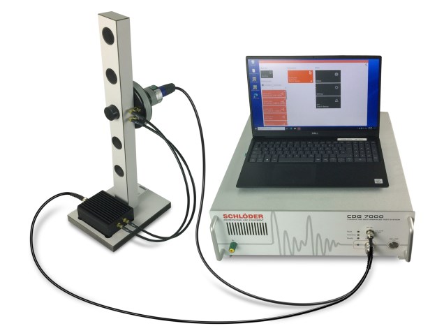
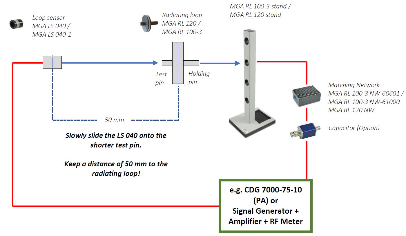
Basic Setup
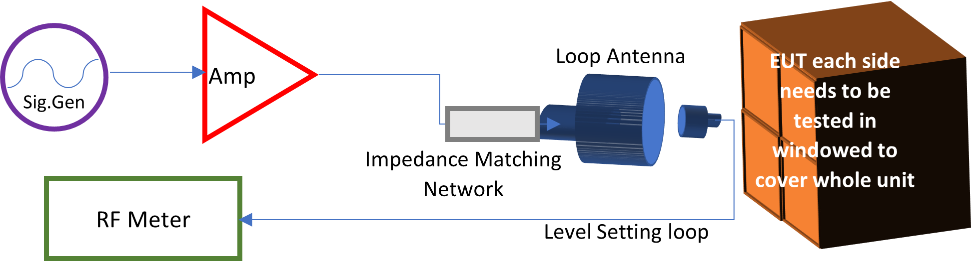
Schlöder has created a system to match this requirement. The system is computer-controlled to set the field level and perform testing with report generation.
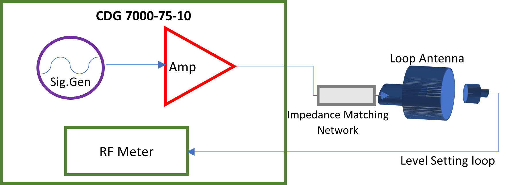
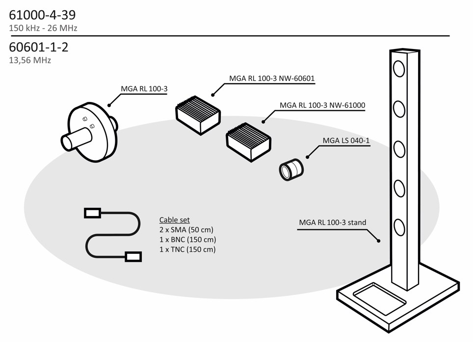
In combination with the CDG 7000-75-10 (PA) and a complete set for the corresponding frequency range, international standards (IEC 60601-1-2 ED. 4.1 / IEC 61000-4-39) for testing medical devices for electromagnetic compatibility can be carried out. These complete sets include a radiating loop, a loop sensor, the matching network for the impedance, and a corresponding stand for the loops.
EN 61000-4-39 describes magnetic field tests in the near field in two frequency ranges from 9 kHz - 150 kHz and from 150 kHz - 26 MHz. For both ranges, complete sets are offered for operation on a typical RF broadband amplifier. (Take the required sets for your tests from the “Equipment or complete sets..” compilation).
|
Frequency range 9 kHz – 150 kHz |
Frequency range 150 kHz – 26 MHz |
|
IEC 61000-4-39 |
IEC 61000-4-39 |
|
RL 120 transmitting coil with LS 040 loop sensor (electrostatic shielded) from MIL-STD-461:
|
For the upper-frequency range, the 61000-4-39 defines a new 100 mm transmitting coil with 3 turns. The generated field is measured with a loop sensor, also newly defined, with a diameter of 40 mm and only 1 turn. In the standard, only the loop sensor is electrostatically shielded. To prevent the radiation of an electric field at higher frequencies, the RL 100-3 is also electrostatically shielded and symmetrically controlled via a balun:
|
|
IEC 60601-1-2 |
IEC 60601-1-2 |
|
In 60601-1-2, magnetic field tests are required with RL 120, but only at two defined frequencies with modified levels and modula¬tions:
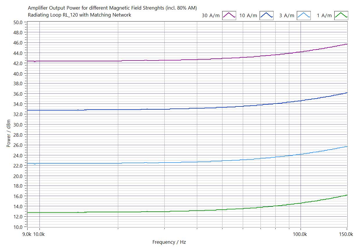
The required power here is max. 46.3 dBm (approx. 43 W). To reduce the power to approx. 43.1 dBm (approx. 20 W), an optional resonant capacitor can be connected in series. |
In 60601-1-2, magnetic field tests are required with RL 100, but only at 13.56 MHz. Level and modulation have also been changed here.
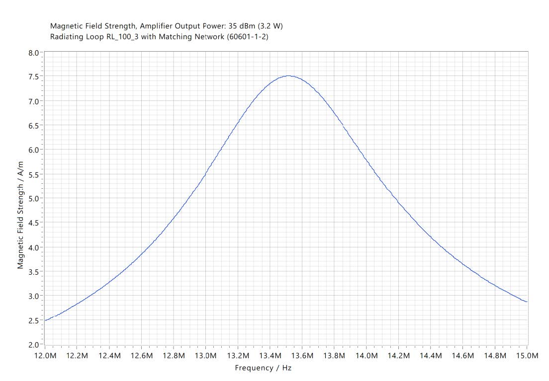
Without resonant network, more than 49.3 dBm (approx. 85 W) is required. With resonant network, the power requirement is reduced to about 35 dBm (approx. 3.2 W). Thus, 30 A/m can be achieved for a short time with about 50 W amplifier power. VSWR is < 1:2 in resonance. |
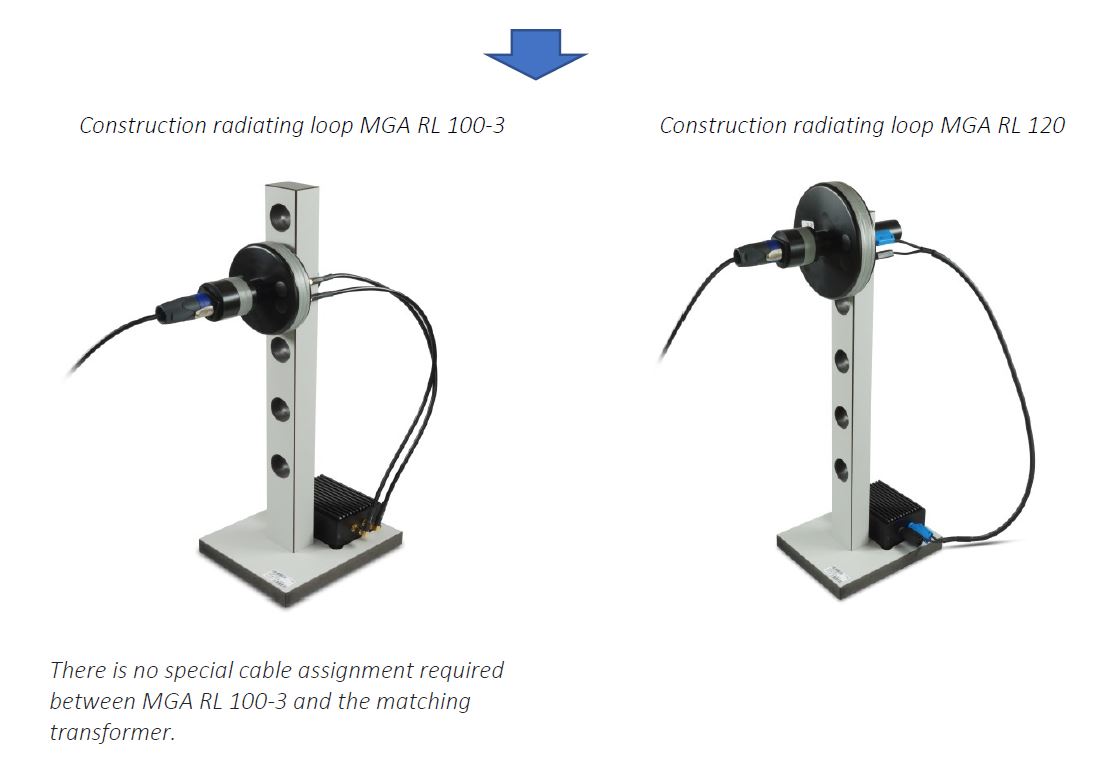
Construction coil set
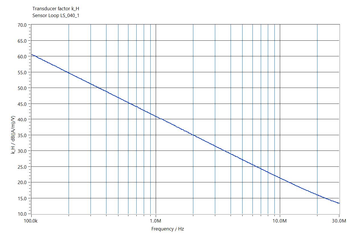
Sensor Loop LS 040-1, Transducer Factor
Radiating loop RL 100-3, Magnetic Field Strength
Magnetic field strength, amplifier output power: 35 dBm (3.2 W)
Radiating loop RL 100-3, with the matching network (60601-1-2)
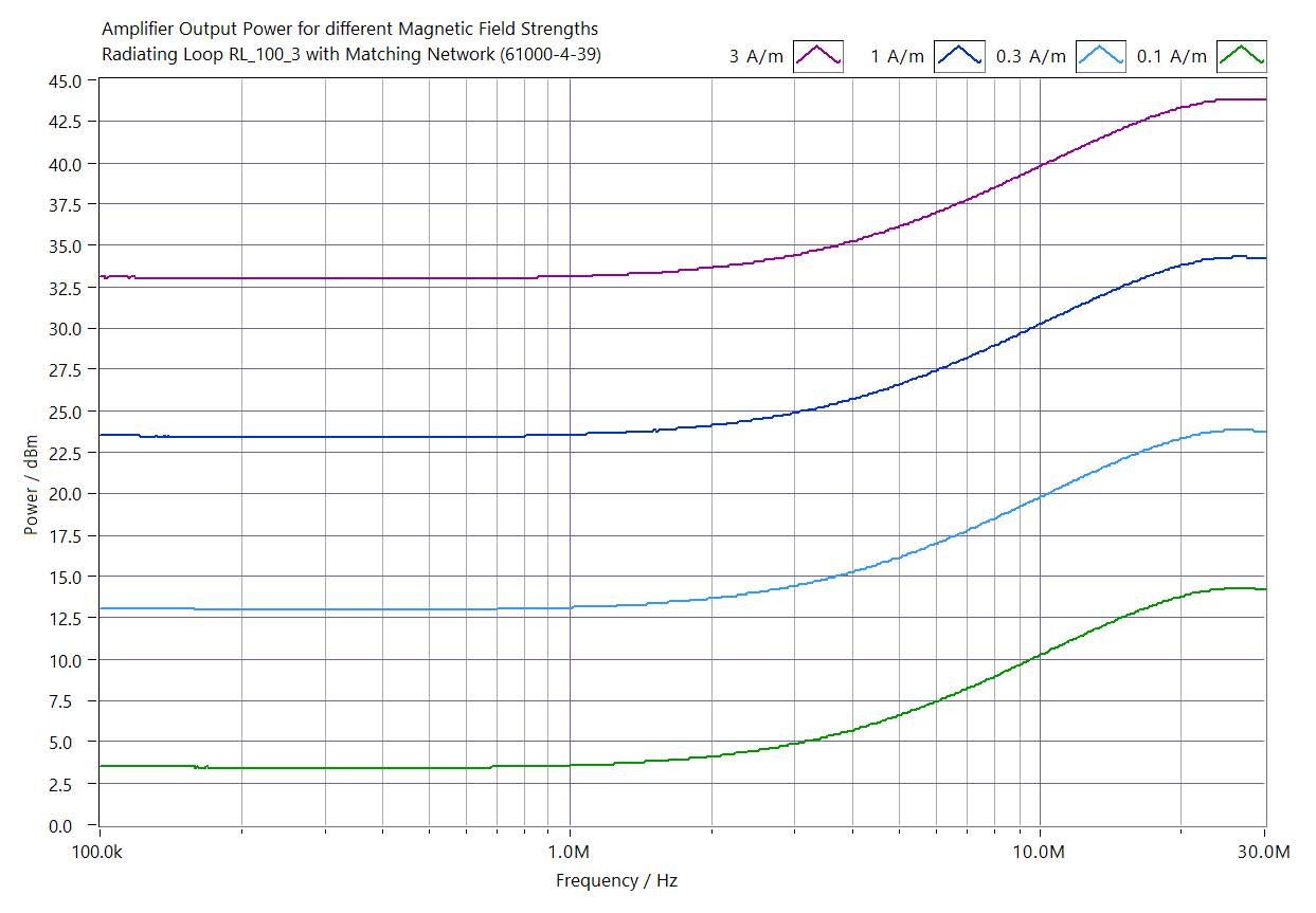
Radiating loop RL 100-3, Amplifier Output Power for different Magnetic Field Strengths
Amplifier output power for different magnetic field strengths
Radiating loop RL 100-3, with the matching network (61000-4-39)
Radiating loop RL 120, Amplifier Output Power for different Magnetic Field Strengths
Amplifier output power for different magnetic field strengths (incl. 80% AM)
Radiating loop RL 120, with matching network
For IEC 60601-1-2, approxi-mately 46.3 dBm is required for 65 A/m at 134.2 kHz with the same setup. This can be realized with the 75W-10 kHz amplifier. With a resonance capacitor in series with the matching network, this required power can be halved to 43.1 dBm.
The following complete sets of equipment is required for the tests:
Generator, software, and measurement
- CDG 7000-75-10 - 10 kHz - 250 MHz, 75 Watt, amplifier, RF Generator, RF Meter x3 (monitored level, forward & reverse power) only IEC 60601-1-2
- Option: PreAmp 150kHz-26MHz -4-39 Preamplifier for CDG 7000-75-10 for tests according to IEC 61000-4-39 (sensor coil LS 040-1 provides too low an output level for the CDG 7000 for the lowest standard levels at low frequencies)
- HELIA 7-MGA software: The system includes all cabling and HELIA 7 software required to meet the standard’s requirements.
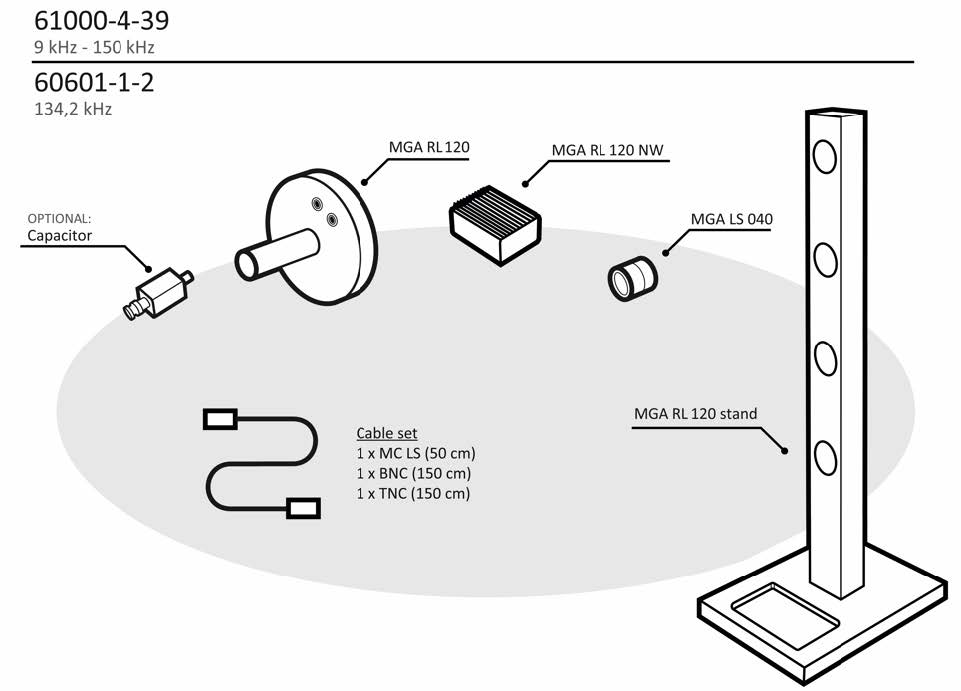
Complete set for frequency range: 9 kHz – 150 kHz
Article No.: Set 9kHz-150kHz -1-2/-4-39
Coil set RL-120 & LS-040 incl. stand and matching network for tests according to IEC 60601-1-2 Ed. 4.1 (30 kHz, 134.2 kHz) and IEC 61000-4-39 (9 kHz to 150 kHz)
- MGA RL 120 – Radiating loop 120 mm as specified in IEC 61000-4-39 for 9 kHz – 150 kHz, IEC / EN 60601-1-2 and MIL-STD-461 / RS101, 3 m cable
- MGA RL 120 NW – Matching Network for MGA RL 120, matches loop to 50 Ohms of the CDG 7000 amplifier acc. to IEC 61000-4-39 and IEC / EN 60601-1-2 for Immunity to magnetic fields 9 kHz - 150 kHz
- MGA RL 120 Stand – Stand for MGA RL 120 for tests
- MGA LS 040 – Loop sensor 40 mm
- Cable set
Complete set for frequency range: 150 kHz – 26 MHz
Article No.: Set 150kHz-26MHz -1-2/-4-39
Coil set RL-100-3 & LS-040-1 incl. stand and matching network for tests according to IEC 61000-4-39 (150 kHz to 26 MHz) and IEC 60601-1-2 (13.56 MHz)
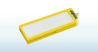
- MGA RL 100-3 – Radiating loop as specified in IEC 61000-4-39 and IEC / EN 60601-1-2 for 150 kHz – 26 MHz
- MGA LS 040-1 – Loop sensor 40 mm that attaches to MGA RL 100-3 at the correct distance of 50 mm as specified in IEC 61000-4-39 and IEC / EN 60601-1-2
- MGA RL 100-3 stand – for tests in stronger magnetic fields
- MGA RL 100-3 NW-60601 – Matching Network 60601 for MGA RL 100-3, matches MGA RL 100-3 to the IEC 60601-1-2 requirements
- MGA RL 100-3 NW-61000 – Matching Network 61000 for MGA RL 100-3, matches MGA RL 100-3 to the IEC 61000-4-39 requirements
- Cable set
Set -4-39 for frequency range: 150 kHz – 26 MHz
Article No.: Set 150kHz-26MHz -4-39
Coil set RL-100-3 & LS-040-1 incl. stand and matching network for tests according to IEC 61000-4-39 (150 kHz to 26 MHz)
- MGA RL 100-3 – Radiating loop as specified in IEC 61000-4-39 and IEC / EN 60601-1-2
- MGA LS 040-1 – Loop sensor 40 mm that attaches to MGA RL 100-3 at the correct distance of 50 mm as specified in IEC 61000-4-39 and IEC / EN 60601-1-2
- MGA RL 100-3 stand – for tests in stronger magnetic fields
- MGA RL 100-3 NW-61000 – Matching Network 61000 for MGA RL 100-3, matches MGA RL 100-3 to the IEC 61000-4-39 requirements
- Cable set
Set -1-2 for frequency range: 150 kHz –26 MHz
Article No.: Set 150kHz-26MHz -1-2
Coil set RL-100-3 & LS-040-1 (incl. stand and matching network) for tests according to IEC 60601-1-2 (13.56 MHz)
- MGA RL 100-3 – Radiating loop as specified in IEC 61000-4-39 and IEC / EN 60601-1-2
- MGA LS 040-1 – Loop sensor 40 mm that attaches to MGA RL 100-3 at the correct distance of 50 mm as specified in IEC 61000-4-39 and IEC / EN 60601-1-2
- MGA RL 100-3 stand – for tests in stronger magnetic fields
- MGA RL 100-3 NW-60601 – Matching Network 60601 for MGA RL 100-3, matches MGA RL 100-3 to the IEC 60601-1-2 requirements
- Cable set
Upgrade for frequency range: 9 kHz – 150 kHz (with existing equipment RL 120 / LS 040)
Article No.: Upgrade 9kHz-150kHz -4-39
- Stand and matching network for coil set RL-120 & LS-040 for tests according to IEC 61000-4-39 (9 kHz to 150 kHz) MGA RL 120 NW – Matching Network for MGA RL 120, matches loop to 50 Ohms of the CDG 7000 amplifier acc. to IEC 61000-4-39 and IEC / EN 60601-1-2 for Immunity to magnetic fields 9 kHz - 150 kHz
- MGA RL 120 Stand – Stand for MGA RL 120 for tests
- Cable set
Capacitor
Article No.: Capacitor 1/2W 134,2 kHz -1-2
The capacitor in housing (resonance matching) for RL-120 with matching network BNC male/ BNC female. When testing for IEC 60601-1-2: 134.2 kHz, 65 A/m, the required power can be halved from 46.3 dBm / 43 W to 43.1 dBm / 20 W with the optional resonance matching. The capacitor in the housing is plugged in front of the matching network.
Added system advantage
- EUT monitoring: with Digital TTL signals & analog 0-10 VDC (automate threshold and report)
- EUT Fail port: Stop test or mark report
- SCPI interface control for universal support (11452-4)
- Conducted immunity testing to IEC 61000-4-6, ISO, MIL, and other standards with the use of additional accessories CDNs, EMC clamps, BCI clamps
More Product Information
- IEC 61000-4-4 Ed.3 standard compliance.
- Pre-check function is installed. Inspection before testing is now easy.
- Normal mode test support. Taking account of field troubles is possible. (option)
- Utilize an outlet box that simplifies EUT connection. (option)
- Compared with conventional products, the size has become compact. (Approximately 67% by volume)
- Easy to understand Panel display reduces mistakes in connecting power cables.
- Software control with Windows. (option)
- Next calibration date can be notified. (Windows software only)
- Employ LCD screen with multi-language support and enhanced operability.
- Maximum output voltage of 5 kV and maximum pulse frequency of 2 MHz allow you to test above the standard test level.
- CDN capacity is increased to single phase type AC 240 V 20 A, single and three phase type to AC 600 V 63 A, supporting wider range of EUT.
- Large capacity CDN (100 A or 150 A) option available for Injection test on various EUT.
- Using coupling clamps, EMS probe kits, you can test the signal lines and evaluate the noise immunity on the PCB. (option)
The Broadband sleeve antenna was developed to efficiently perform proximity radiation immunity testing.
The international standards ISO11451-3/ISO11452-9 stipulate proximity radiation immunity testing methods that assume electromagnetic interference when wireless transmitters such as smartphones and Wi-Fi devices are placed in close proximity to other electronic devices.
This product is a small, lightweight, high-gain antenna used in these standards that covers a wide bandwidth and has good radiation characteristics. Since it can be used in the wide band from 5GHz to 8GHz, it can be used to perform proximity radiation immunity testing assuming wireless LAN in the 6GHz band (up to 7.125GHz).
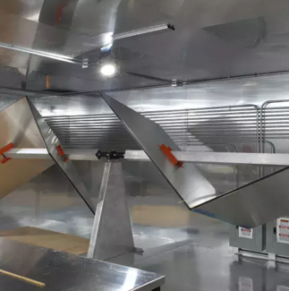
Our reverberation chamber is particularly suited for immunity testing for EMC measurement and special applications for very high-field strength applications (200V/m - 7000V/m). The paddle system ensures that the widest range of frequencies and particularly low frequency performance is maximized. This system meets testing requirements of the IEC61000-4-21 EMC testing specification.
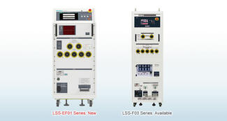
LSS-EF01 series
This simulator evaluates the immunity of electronic equipment by simulating "highenergy induced lightning noise" induced in power distribution lines and communication lines due to fluctuations in the earth's potential caused by lightning strikes. This is an entry model of the LSS-F03 series. (Maximum output voltage 6kV)
LSS-F03 series
A tester simulatively generates "High energy induced lightning noise" which induced to distribution lines or communication lines by ground potential fluctuation caused by lightning strikes.
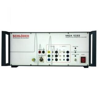
The compact magnetic field generator and analyzer MGA 1033 allows susceptibility tests against magnetic fields from DC to 250 kHz according to the standard EN 55103-2 and their measurement according to EN 55103-1. In addition, EMC tests are possible according to various standards such as automotive, avionic and MIL-STD.; Generation of magnetic fields from DC to 250 kHz; Field strength up to 1000 A/m; EN 55103-1/2, MIL-STD 461, Automotive etc.; Accessories: Loop sensors, Helmholtz coils etc.;
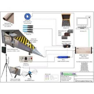
Absolute EMC has designed low-cost pre-compliance systems to meet a wide range of RF emissions and immunity needs. Some form of pre-complaint testing is a must for any company that needs to demonstrate their product for EMC compliance. This enables companies to be responsive when issues happen and to also be proactive before going to the lab to better your chances of passing the first time.
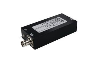
- Ideal for applications requiring high ENR and immunity to large incident RF power
- Low VSWR
- Built-in isolator
The NC3400 Series coaxial AWGN noise sources are an excellent choice for applications requiring high ENR and immunity to large incident RF power, such as ATE, radiometer, and radar systems. The calibration accuracy and flatness of the NC3400 Series noise sources are enhanced by their low VSWR. The built-in isolator provides almost constant output impedance as the noise source bias is switched on and off. The isolator also protects the noise diode from incident RF power (consult the factory for higherpower units).
An SMA female connector is standard for the RF output and a BNC female connector is standard for the bias input. Other connectors are available as options.
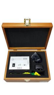
- Frequency Range:
- 10 kHz - 30 MHz Conducted
- 5 MHz - 1GHz Radiated
- Frequency step:
- 10/500 kHz switchable CE
- 5/10 MHz switchable RE
- Includes: Generator, antenna, charger, wood case
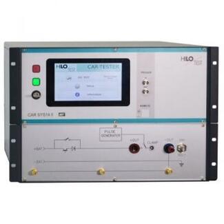
The EMC test system is designed for testing electromagnetic immunity of the electrical installation of vehicles and components against supply line transients. EMC - Test Equipment for the electrical installation of vehicles.
- Pulse #1 1-5/2000us, 600 V
- #1 1-5/1000us, 600 V
- Pulse #2a 1 / 50us, 600 V
- Pulse #3 5/100 ns, 800 V
Absolute EMC
Website
Absolute EMC LLC is a premier North American provider of electromagnetic compatibility (EMC) expertise and test equipment. They deliver end to end consulting—covering IEC, MIL STD, CISPR, and automotive standards—hands on training for all EMC and RF test instruments, and turnkey test system design and integration. Leveraging decades of experience with every major manufacturer and the latest technologies, they also offer strategic guidance on equipment selection, market trends, and procurement to help you maximize the performance and ROI of your EMC investments.