You design the future. We help you make it happen.
Teledyne LeCroy - T3VNA Vector Network Analyzers
- Vector Network Analyzer Frequency Range from 10 MHz up to 3.2 GHz
- Spectrum Analyzer Frequency Range from 9 kHz up to 3.2 GHz
- -156 dBm/Hz Displayed Average Noise Level (Typ.)
- -98 dBc/Hz @10 kHz Offset Phase Noise (1 GHz, Typ.)
- Total Amplitude Accuracy < 1.2 dB
- 1 Hz Minimum Resolution Bandwidth (RBW)
- All-Digital IF Technology
- Standard Preamplifier
- Distance to fault capability using VNA time domain analysis
- Up to 1.5 GHz Tracking Generator Kit
- Built-in Advanced Measurement capability (CHP, ACPR, OBW, CNR, TOI, etc)
- 10.1 lnch WVGA (1024 x 600) Display
The Teledyne Test Tools range of T3VNA Vector Network Analyzer has a Vector Network Analysis frequency range of 100 kHz up to 3.2 GHz and a Spectrum Analysis frequency range from 9 kHz up to a maximum of 3.2 GHz. The small footprint and easy user interface is augmented by a high performance specification with many advanced measurement functions and capabilities.
Teledyne Test Tools T3VNA family of Vector Network Analyzers consists of models with various Vector Network Analysis frequency ranges from as low as 100 kHz up to 3.2 GHz and Spectrum Analysis frequency range from 9 kHz up to 3.2 GHz depending on model.
|
Products |
|
|---|---|
|
Vector Network Analyzer 9KHz-3.2GHz. Includes Adv Meas Kit, Distance To Fault Opt, Cal and Utl Kits Limited Availability |
|
More Product Information

The DigRF 3G and v4 decode are the ideal tools for powerful system level protocol debug as well as problem solving for signal quality issues. The DigRF decodes add a unique set of tools to your oscilloscope, simplifying how you design and debug MIPI digital RF systems.
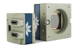
- Industry’s latest CMOS image sensors
- Simplified set-up with field proven Sapera LT software featuring CamExpert
- Engineered to accommodate industrial environment with a ruggedized screw mount SDR connectors
- GenICan GenCP compliant
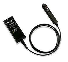
- Ideal probe for up to 48 V power conversion
- 250, 500 MHz and 1 GHz bandwidth
- 80 V dynamic range
- 60 V common mode
- Highest accuracy
- 0.5% gain accuracy
- Precision gain calibration
- Best LF flatness (0.1 dB)
- Lowest noise and highest rejection
- Wide variety of tips
- High performance solder-in
- Browser
- Single pins and header
- Mini and micro grabbers
- Socketed connections
- High temp solder-in
- Y-banana adaptor
- ProBus active probe interface

- Highest resolution – 12 bits all the time
- More capability – integrates multiple instruments into one
- Comprehensive probe support – supports over 30 probes in 9 categories
- MAUI with OneTouch user interface for intuitive and efficient operation

- 2000 Vrms input
- 6000 Vpeak transients
- Up to 500 MHz bandwidth
- Ideal for Surge/EFT testing
High voltage single-ended passive probes are suitable for a wide range of applications where ground-referenced high-voltage measurements must be made safely and accurately. There is also a sense pin to automatically configure the oscilloscope for use with the probe.

Transmission line probes are a special type of passive probe designed for use at very high frequencies. They replace the high impedance probe cable found in a traditional passive probe with a precision transmission line, with a characteristic impedance that matches the oscilloscope input (50 Ohm). This greatly reduces the input capacitance to a fraction of a picofarad, minimizing the loading of high frequency signals. A matching network at the tip increases the DC input resistance. While they have lower DC input resistance than a traditional passive probe (usually 500 Ohm) to 1kOhm), the input impedance of these probes remains nearly constant over their entire frequency range. A traditional /10 passive probe will have a 10 MOhm) input impedance at DC, however this impedance drops rapidly with frequency, passing below the input impedance of a transmission line probe at less than 100 MHz.

- HD4096 technology provides 12-bit resolution up to 8 GHz and 20 GS/s
- Up to 5 Gpts of acquisition memory enables detailed viewing of long events
- 15.6" 1900 x 1080 Full HD capacitive touchscreen
- New ProBus2 input supports up to 8 GHz bandwidth and direct compatibility with a wide variety of existing ProBus probes - 50Ω and 1MΩ coupling modes support all input types on a single connector
- MAUI with OneTouch user interface for intuitive and efficient operation
- Deep toolbox enables and simplifies complex analysis
- Intuitive navigation to quickly find important features in long waveforms
- Zone Trigger – Simple Triggering for Complex Signals
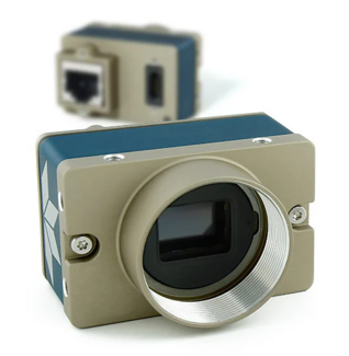
- Uses standard PC Ethernet port & hardware
- Supports cable lengths up to 100 m (CAT-5e or CAT-6)
- Simplified set-up with field proven Sapera LT software featuring CamExpert
- Engineered to accommodate industrial environment with a ruggedized screw mount RJ-45 connector
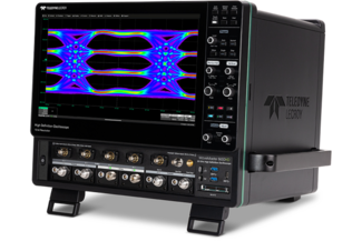
WaveMaster 8000HD is the only high speed oscilloscope designed for all stages of product development, whether first-silicon characterization, link validation over channels, or debugging across the entire the protocol stack. No other high speed oscilloscope supports more engineering tasks with more unique tools.
- Exceptional signal characterization performance
- Unrivaled validation and debug capabilities
- Comprehensive serial data expertise
Teledyne LeCroy
Website
12bit MSO's 40 Mhz to 100 GHz, Probes, Series Network & Logic Analyzers
